Monday, April 1, 2019

Check whether two numbers of opposite sign or not

#include<stdbool.h>
#include<stdio.h>


bool CheckOppositeSign(int a, int b)
{
        bool bRetValue = 0;
        bRetValue = ((a ^ b) < 0); // 1 iff a and b have opposite signs
        return bRetValue;
}


int main()
{
        int a = 0,b=0;
        bool bRetValue;
        //ENTER THE VALUE OF a & b

        printf("Enter the Value of a = ");
        scanf("%d",&a);
        printf("\nEnter the Value of b = ");
        scanf("%d",&b);

        bRetValue = CheckOppositeSign(a, b); // check signs of a & b

        if (true == bRetValue)
                printf ("\nIntegers have the opposite sign\n\n");
        else
                printf ("\nInteger have the same sign\n\n");

        return 0;
}

Saturday, March 30, 2019

Check whether an Integer has an Alternate Pattern Bit pattern or Not

#include <stdio.h>

int main(void) {
int num, x, y, count = 0;

    printf("enter the number:");
    scanf("%d", &num);
    x = num << 1;
    y = x ^ num;
    y = y + 1;
 
    y =  isPowerOfTwo(y);
 
    if(y)
        printf("true");
    else
        printf("false");
}

int isPowerOfTwo (unsigned int x)
{
       return ((x > 0) && ((x & (~x + 1)) == x));
}

Multiply an Integer with 3.5 using bitwise operation

 the following operation is actually  (2 *data) + data + (data/2).


#include <stdio.h>
int main()
{
  unsigned int data = 10; 
  
  data = (data<<1) + data + (data>>1);; // equivalent to data * 3.5
  
  printf("data = %d\n", data);
  
  return 0;

}

Friday, March 29, 2019

RISC and CISC Architecture

RISC (Reduced Instruction Set Computer) Architecture 

The microcontroller architecture that utilizes small and highly optimized set of instructions is termed as the Reduced Instruction Set Computer or simply called as RISC. It is also called as LOAD/STORE architecture.
RISC Architecture


Typical Features of RISC Architecture

  • Pipelining technique of RISC, executes multiple parts or stages of instructions simultaneously such that every instruction on the CPU is optimized. Hence, the RISC processors have Clock per Instruction of one cycle, and this is called as One Cycle Execution.
  • It optimizes the usage of register with more number of registers in the RISC and more number of interactions within the memory can be prevented.
  • Simple addressing modes, even complex addressing can be done by using arithmetic AND/ OR logical operations.
  • It simplifies the compiler design by using identical general purpose registers which allows any register to be used in any context.
  • For efficient usage of the registers and optimization of the pipelining uses, reduced instruction set is required.
  • The number of bits used for the opcode is reduced.
  • In general there are 32 or more registers in the RISC.

Advantages of RISC processor architecture

  • Because of the small set of instructions of RISC, high-level language compilers can produce more efficient code.
  • RISC allows freedom of using the space on microprocessors because of its simplicity.
  • Instead of using Stack, many RISC processors use the registers for passing arguments and holding the local variables.
  • RISC functions uses only a few parameters, and the RISC processors cannot use the call instructions, and therefore, use a fixed length instructions which are easy to pipeline.
  • The speed of the operation can be maximized and the execution time can be minimized.
  • Very less number of instruction formats (less than four), a few number of instructions (around 150) and a few addressing modes (less than four) are needed.

Drawbacks of RISC processor architecture

  • With the increase in length of the instructions, the complexity increases for the RISC processors to execute due to its character cycle per instruction.
  • The performance of the RISC processors depends mostly on the compiler or programmer as the knowledge of the compiler plays a major role while converting the CISC code to a RISC code; hence, the quality of the generated code depends on the compiler.
  • While rescheduling the CISC code to a RISC code, termed as a code expansion, will increase the size. And, the quality of this code expansion will again depend on the compiler, and also on the machine’s instruction set.
  • The first level cache of the RISC processors is also a disadvantage of the RISC, in which these processors have large memory caches on the chip itself. For feeding the instructions, they require very fast memory systems.

CISC (Complex Instruction Set Computer) Architecture

The main intent of the CISC processor architecture is to complete task by using less number of assembly lines. For this purpose, the processor is built to execute a series of operations. Complex instruction is also termed as MULT, which operates memory banks of a computer directly without making the compiler to perform storing and loading functions.
Features of CISC Architecture
  • To simplify computer architecture, CISC supports microprogramming.
  • CISC have more number of predefined instructions which makes high level languages easy to design and implement.
  • CISC consists of less number of registers and more number of addressing modes, generally 5 to 20.
  • CISC processor takes varying cycle time for execution of instructions – multi-clock cycles.
  • Because of the complex instruction set of the CISC, the pipelining technique is very difficult.
  • CISC consists of more number of instructions, generally from 100 to 250.
  • Special instructions are used very rarely.
  • Operands in memory are manipulated by instructions.
CISC Architecture

Advantages of CISC architecture

  • Each machine language instruction is grouped into a microcode instruction and executed accordingly, and then are stored inbuilt in the memory of the main processor, termed as microcode implementation.
  • As the microcode memory is faster than the main memory, the microcode instruction set can be implemented without considerable speed reduction over hard-wired implementation.
  • The entire new instruction set can be handled by modifying the microprogram design.
  • CISC, the number of instructions required to implement a program can be reduced by building rich instruction sets and can also be made to use slow main memory more efficiently.
  • Because of the superset of instructions that consists of all earlier instructions, this makes micro coding easy.

Drawbacks of CISC

  • The amount of clock time taken by different instructions will be different – due to this – the performance of the machine slows down.
  • The instruction set complexity and the chip hardware increases as every new version of the processor consists of a subset of earlier generations.
  • Only 20% of the existing instructions are used in a typical programming event, even though there are many specialized instructions in existence which are not even used frequently.
  • The conditional codes are set by the CISC instructions as a side effect of each instruction which takes time for this setting – and, as the subsequent instruction changes the condition code bits – so, the compiler has to examine the condition code bits before this happens.

RISC vs. CISC

  • The wasting cycles can be prevented by the programmer by removing the unnecessary code in the RISC, but, while using the CISC code leads to wasting cycles because of the inefficiency of the CISC.
  • In RISC, each instruction is intended to perform a small task such that, to perform a complex task, multiple small instruction are used together, whereas only few instructions are required to do the same task using CISC – as it is capable of performing complex task as the instructions are similar to a high-language code.
  • CISC is typically used for computers while RISC is used for smart phones, tablets and other electronic devices.
  • RISC processors are cheaper when compared to CISC.
  • RISC uses the Hardwired control unit for Instruction execution which is faster and CISC uses the Microprogrammed control unit. Micro-programmed control unit is slower in speed because of the time it takes to fetch microinstructions from the control memory.[Refer-https://www.geeksforgeeks.org/computer-organization-hardwired-vs-micro-programmed-control-unit/]

Thursday, March 28, 2019

Virtual Memory - Part 2

In the Virtual Memory - Part 1, we have discussed paging and virtual memory concepts. However, it didn't cover some of the key concepts of the Linux Kernel and Paging. This article is all about extending our general understanding of Virtual Memory and Paging concepts to Linux Kernel Memory Management area. This also covers the L1/L2 or first/second level page table concepts.

In Linux, the kernel uses virtual addresses, as userspace processes do. This is not true in all OS's

Three kinds of Virtual Addresses exists in Linux systems

1.Kernel Addresses:
  • Kernel Logical Address. 
  • Kernel Virtual Address.
 2. Userspace Address:
  • User Virtual Address.

The below figure shows the "Virtual Address Space" for a typical 32-bit Linux system.  In a 64-bit system of ARM typically the split is higher - 0x8000000000000000


The process address space is described by the mm_struct struct meaning that only one exists for each process and is shared between userspace threads. In fact, threads are identified in the task list by finding all task_structs which have pointers to the same mm_struct. A unique mm_struct is not needed for kernel threads as they will never page fault or access the userspace portion. The only exception is page faulting within the vmalloc space. The page fault handling code treats this as a special case and updates the current page table with information on the master page table. As a mm_struct is not needed for kernel threads, the task_structmm field for kernel threads is always NULL. For some tasks such as the boot idle task, the mm_struct is never set up but for kernel threads, a call to daemonize() will call exit_mm() to decrement the usage counter.


Linux Page Table and Page Size 


The hardware (specifically, the MMU, which is part of the CPU) determines what page sizes are possible. There is no relation to the processor register size and only an indirect relation to the address space size (in that the MMU determines both). Typically this is 4KB.


Since we have a virtual address space of 2^32 and each page size is 2^12, we can store (2^32/2^12) = 2^20 pages. Since each entry into this page table has an address of size 4 bytes, then we have 2^20*4 = 4MB. So the page table takes up 4MB in memory.


The page size is a compromise between memory usage, memory usage and speed.
  • A larger page size means more waste when a page is partially used, so the system runs out of memory sooner.
  • A deeper MMU descriptor level means more kernel memory for page tables.
  • A deeper MMU descriptor level means more time spent in page table traversal.

KERNEL ADDRESS SPACE


Kernel Logical Address space

As you can see from the above diagram that the kernel address space is split into One-One mapped region which is called as "Kernel Logical Address space". This is an area where the translation of virtual to physical is fixed and doesn't go through the overhead of memory management logic. This means virtually-contiguous regions are by nature also physically contiguous. Note as this memory is out of the logic of mappings and cannot be swapped out makes it suitable for DMA allocations. 

Kernel logical address space includes:
             ● Memory allocated with kmalloc() and most other allocation methods
             ● Kernel stacks (per process)

Kernel Logical addresses can be converted to and from physical addresses using the macros: __pa(x)  and  __va(x)


For low-memory systems (below ~1G of RAM) Kernel Logical address space starts at PAGE_OFFSET and goes through the end of physical memory. Hence all memory of  
the kernel is having a fixed mapping for a system with RAM below 1GB.

For large memory systems (more than ~1GB RAM), not all of the physical RAM can be one-to-one mapped into the kernel's address space. Kernel address space is the top 1GB of virtual address space, by default. Further, 128 MB is reserved at the top of the kernel's memory space for non-contiguous allocation which is known as "Kernel Virtual Address Space" or Vmalloc area(description is as below). Hence the size of  "Kernel Logical Address Space for a system with more than 1GB RAM becomes 896 MB (however this excluded 64-bit and 4GB RAM systems)

Kernel Virtual Addresses

These are addresses in the region above the kernel logical address mapping. These are used for non-contiguous memory mappings because they could be virtual contiguous in nature. Often for large buffers which could potentially be unable to get physically contiguous regions allocated. Also referred to as the vmalloc() area. Larger memory in this area is easier to allocate however as this is physically non-contiguous is not suitable for DMA.

The kernel uses lazy allocation of physical memory.
When memory is requested by userspace, physical memory is not allocated until it's touched.This is an optimization, knowing that many userspace programs allocate more RAM than they ever touch(Buffers, etc)


RECAP: Page Fault 

A Page Fault is an exception generated by MMU when a process tries to access a page whose entry is not present in TLB or it doesn't have enough permission to access that page.Usually, the process reason for a page fault is suspended and if the page fault handler can recover; the kernel can resume the process later if the handler is able to map the virtual to physical address.

Supporting topic - 64-bit processing

In computer architecture, 64-bit computing is the use of processors to have datapath widths, integer size, and memory address widths of 64 bits (eight octets). Also, 64-bit computer architectures for central processing units (CPUs) and arithmetic logic units (ALUs) are those that are based on processor registers, address buses, or data buses of that size. From the software perspective, 64-bit computing means the use of code with 64-bit virtual memory addresses. However, not all 64-bit instruction sets support full 64-bit virtual memory addresses; x86-64 and ARMv8, for example, support only 48 bits of virtual address, with the remaining 16 bits of the virtual address required to be all 0's or all 1's, and several 64-bit instruction sets support fewer than 64 bits of physical memory address.

Difference between TLB and Page Table
The TLB is a cache that holds (likely) recently used pages. The principle of locality says that the pages referenced in the TLB are likely to be used again soon. This is the underlying idea for all caching. When these pages are needed again, it takes minimal time to find the address of the page in the TLB. The page table itself can be enormous, so walking it to find the address of the needed page can get very expensive.

to be continued ... with Userspace Process Address Space in more detail.

References :-
                   https://stackoverflow.com/questions/16323890/calculating-page-table-size

Wednesday, January 16, 2019

Virtual Memory - Part 1

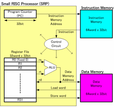
Older and simple systems have a "FLAT memory model"
Flat memory model or linear memory model refers to a memory addressing paradigm in which memory appears to the program as a single contiguous address space. The CPU can directly (and linearly) address all of the available memory locations without having to resort to any sort of memory segmentation or paging schemes.
Memory management and address translation can still be implemented on top of a flat memory model in order to facilitate the operating system's functionality, resource protection, multitasking or to increase the memory capacity beyond the limits imposed by the processor's physical address space, but the key feature of a flat memory model is that the entire memory space is linear, sequential and contiguous from address zero to MaxBytes.
In a simple controller, or in a single-tasking embedded application, where memory management is not needed nor desirable, the flat memory model is the most appropriate, because it provides the simplest interface from the programmer's point of view, with direct access to all memory locations and minimum design complexity.

The problem with this type of allocation is (external) fragmentation of memory: sometimes, there is enough free memory in the system, but it is fragmented over several locations so that a contiguous block cannot be found to satisfy a request.
  • Memory and Peripheral Share.
    • Memory will be mapped to ONE part
    • Peripherals will be mapped to another
  • All processes and OS share the same memory.
    • No Memory protection. User-space and corrupt Kernel Memory.

Another Advance thing is  "PAGED memory model"

Two important feature of Paged memory model is "PAGING" and "Virtual Memory". This is implemented in the Memory Management Subsystem of any operating system. We will discuss more on "LINUX-ARM" based memory management in this article.

This is a memory management technique that allows non-contiguous memory allocations to processes and avoids the problem of external fragmentation. Most modern operating systems use paging. With paging, the physical memory is divided into frames, and the virtual address space of a process is divided into logical pages

  • Suitable for multitasking, general operating system design, memory/resource protection and allocation.
  • More CPU real estate, somewhat lower speed
  • More complex to program.
  • Rigid page boundaries, not always the most memory efficient.


Features of the model

  1. Virtual Memory is used here where Virtual Addresses are mapped to Physical Addresses using MMU. 
    • Maps Virtual Address to Physical RAM area.
    • Maps Virtual Address to Peripheral Device Memory
      • GPU, PCI On-SOC IP blocks are examples.
  1. Each process can have a different memory mapping. One process address space is separate from others.
  2. Kernel Area is invisible to User-space Area
  3. Physical RAM area can be mapped to multiple process address space to create shared memory among processes.
  4. Memory mapping may have read/write permissions.
  5. Memory can be moved/swapped in/out for disks.
  6. Avoid the problem of external fragmentation since this is non-contiguous memory approach.
Memory Management Unit and Virtual Memory

The memory management unit(MMU) hardware is responsible for implementing Virtual Memory.
  • This sits between the CPU core and Physical Memory.
  • Most often MMU is part of CPU core itself. [As in case of ARM]
  • Separate from RAM controller - DDR controller is a separate IP.
  • Transparently handles all memory accesses from load-store instructions.
    • Maps access from Virtual Address to system RAM.
    • Maps access from Virtual Address to Memory Mapped I/O or Hardware
    • Handles Permission and Generates exception on illegal access or invalid virtual address. In other words, If the virtual address is not in the TLB, the MMU will generate a page fault exception and interrupt the CPU.


                              Image by Prof Matt Welsh, Harvard University


How does  Virtual Address get created?


  1. Processor core generates the Virtual Address.
  2. MMU takes the upper bits of Virtual Address and replaces them with the contents of the relocation register and thus it gets the Physical Address.
  3. The lower portion of the virtual address is offset that translates an address in Physical Memory.
  4. A single relocation register can translate a singe area of  virtual memory called as Page. The corresponding physical memory area is called a Page Frame.
How does so many Pages are handled in a multithreading environment?

A single relocation register can translate only a single Page into a PageFrame. The ARM MMU hardware has multiple relocation registers supporting the translation of virtual to physical memory. The MMU needs many relocation registers to map so many pages. ARM MMU has a set of 64 relocation register which caches(temporary stores) the translation of recently accessed page which is called TLB(Translation Look-Aside Buffer).

In addition to TLB, the Linux kernel maintains a Page Table(Tables in Main Memory), this also has the mapping data for the recently accessed page again used by MMU. Each entry in the Page table also has details on access permission/cache/write buffer configurations etc.

Why do we need TLB?  Can we only use Linux's Page table?

The TLB is used to reduce the time taken to access the memory locations in the page-table method. The TLB is a cache or temporary storage of the Linux's page table, representing only a subset of the page-table contents.


TLB is checked for Page Faults:-

  1. If the virtual address is not in the TLB, the MMU will generate a page fault exception and interrupt the CPU.
  2. If the address is in the TLB, but the permissions are insufficient, the MMU will generate a page fault.


Note: MMU is a piece of Hardware, it doesn't act automatically. Again Kernel has relevant code to use MMU for implementing the complete Memory Management functionality. MMU can be configured/initialized/switched off just like other On-chip components.


Summary:

Flat Memory Model is like where there is one-to-one mapping Virtual to Physical Address. This is simple without any overhead of Memory Management. However, this approach doesn't work for complex multithreaded and multi-core system as there should be some external software/hardware component who has to manage the memory for better usage among so many processes.
  • Risk of Fragmentation of Memory.
  • Risk of Corruption of Other Process Address Space.
  • Lesser control in applying write/read permissions for memory etc.
Paged Memory Model not only gives us more control/security on Memory and its usage - per process wise but also it relives from the risk of over-fragmentation This becomes even more valid especially in event-driven embedded systems where a system is rarely restarted often - an example would be a mobile phone software. 

References:-

  1. ARM System Developer's Guide by Andrew,Dominic and Chris
  2. https://www.cse.iitb.ac.in/~mythili/teaching/cs347_autumn2016/